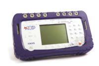
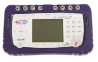
CALYS 150 (1) - AOIP, Instrumentation de test et mesure, contrôle moteur
CALYS 150 (2) - AOIP, Instrumentation de test et mesure, contrôle moteur
CALYS 150 (3) - AOIP, Instrumentation de test et mesure, contrôle moteur
CALYS 150 (4) - AOIP, Instrumentation de test et mesure, contrôle moteur
CALYS 150 (5) - AOIP, Instrumentation de test et mesure, contrôle moteur
CALYS 150 (6) - AOIP, Instrumentation de test et mesure, contrôle moteur
CALYS 150 (7) - AOIP, Instrumentation de test et mesure, contrôle moteur
CALYS 150 (8) - AOIP, Instrumentation de test et mesure, contrôle moteur
CALYS 150 (9) - AOIP, Instrumentation de test et mesure, contrôle moteur
CALYS 150 (10) - AOIP, Instrumentation de test et mesure, contrôle moteur
CALYS 150 (11) - AOIP, Instrumentation de test et mesure, contrôle moteur

CALYS 150

picto fleche Advanced documenting multifunction calibrator thermometer

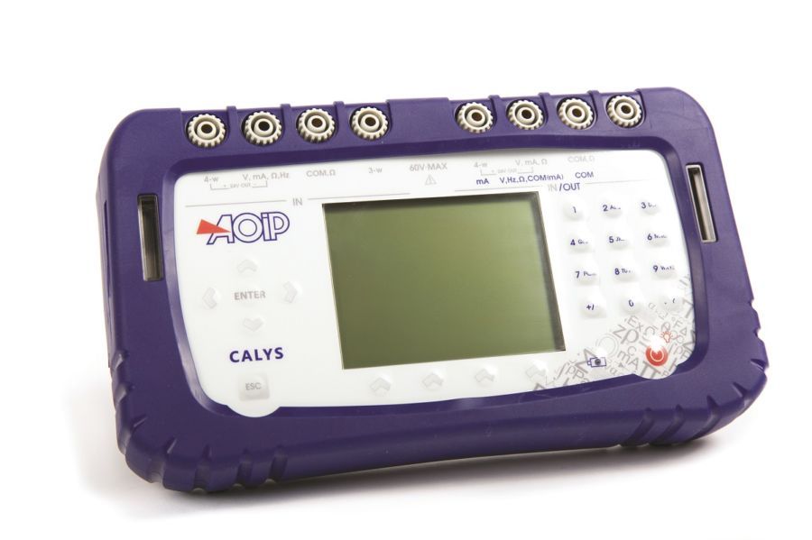
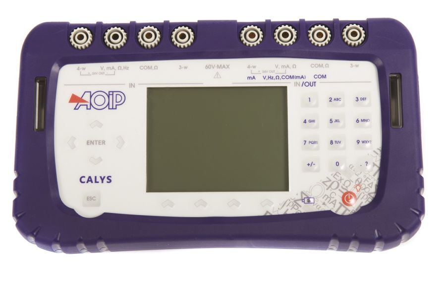
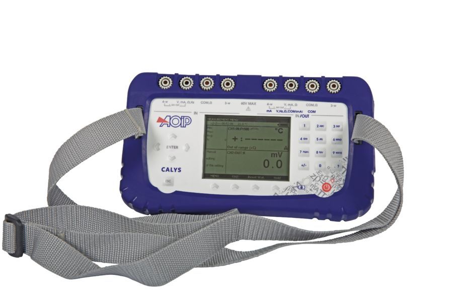
CALYS 150, most advanced documenting multifunction instrument of the range, works not only as a simulator (IN / OUT) but also as a dual channel thermometer (IN / IN). It calibrates HART transmitters (HART communicator integrated) and thermistors.

Ask a question
Get a call

CALYS 150 field documenting multifunction calibrator is the top instrument of the range. It is the perfect tool for advanced process maintenance and use on test bench in all industries. Suitable for all field and lab measurements, it can simultaneously measure and generate over two isolated channels various signals of temperature, resistance, process, pressure and frequency in one single instrument. CALYS 150 does not only work as a simulator (IN / OUT) but also as a dual channel thermometer (IN / IN) to perform comparison calibration. It calibrates HART transmitters (HART communicator integrated into ACL500 modem) and thermistors. Providing extended functionalities (temperature simulation, scaling, steps, synthesizer, statistical functions…) and audit trails, CALYS 150 complies with both 21 CFR Part 11 and NADCAP Heat Treatment standards and makes advanced data exploitation and full data traceability easier. High performances for CALYS 150, for advanced use:

  • Temperature Up to 0.005 % RDG
  • Resistance Up to 0.006 % RDG and 50 KΩ range
  • Current: Up to 0.007 % RDG and 100 mA range + Loop Supply 24 V
  • Voltage: Up to 0.005 % RDG and 50 V range
  • Frequency: Up to 0.01 % RDG and 100 KHz range
  • Pressure: With an external pressure module (comparison calibration with a pressure pump)

Using this user-friendly instrument, calibration tasks can be quickly carried out over the whole process chain. Take the 900 g documenting process calibrator to the field with you during the whole week with 10 calibration procedures stored in the device. Run the procedure after connecting the probes to the instrument (Easy connect system®) and save the results for onsite easy and quick calibration. Back to the office, you can then upload the data on a computer in order to issue customized calibration certificates with dedicated calibration software DATACAL. IP 54, fully protected by an antichoc rubber holster, CALYS 150 integrates "easyconnect" terminals and a wide backlite display that makes it easy to use in any severe or dark conditions. When used with an external pressure module (ref. ACL433), CALYS 150 can measure and simulate pressure (comparison calibration with a pressure pump). CALYS 150 has also the capability to drive baths and dry-blocks when associated with the specific cable (ref. ACL600).

Easy connection system

CALYS_Easyconnect pressed_BD 
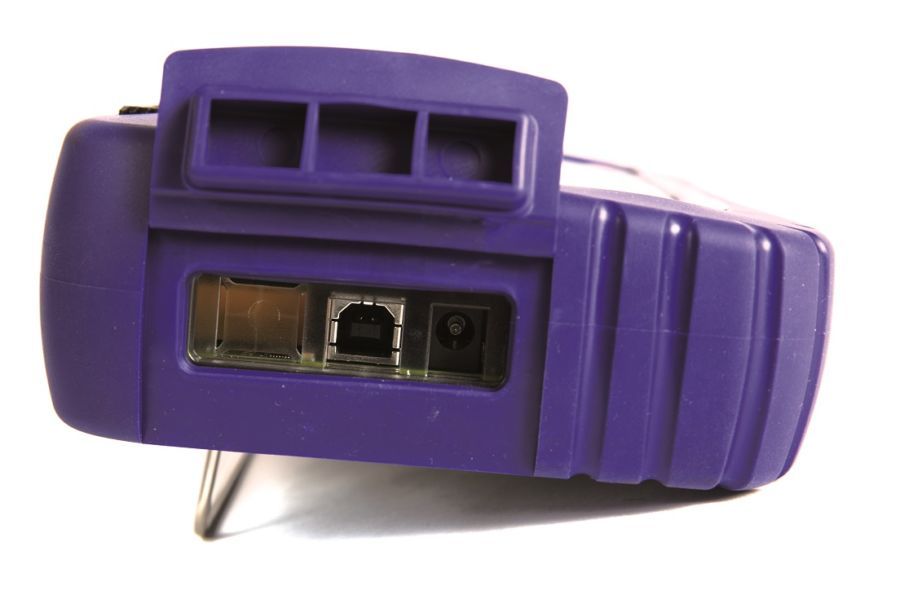
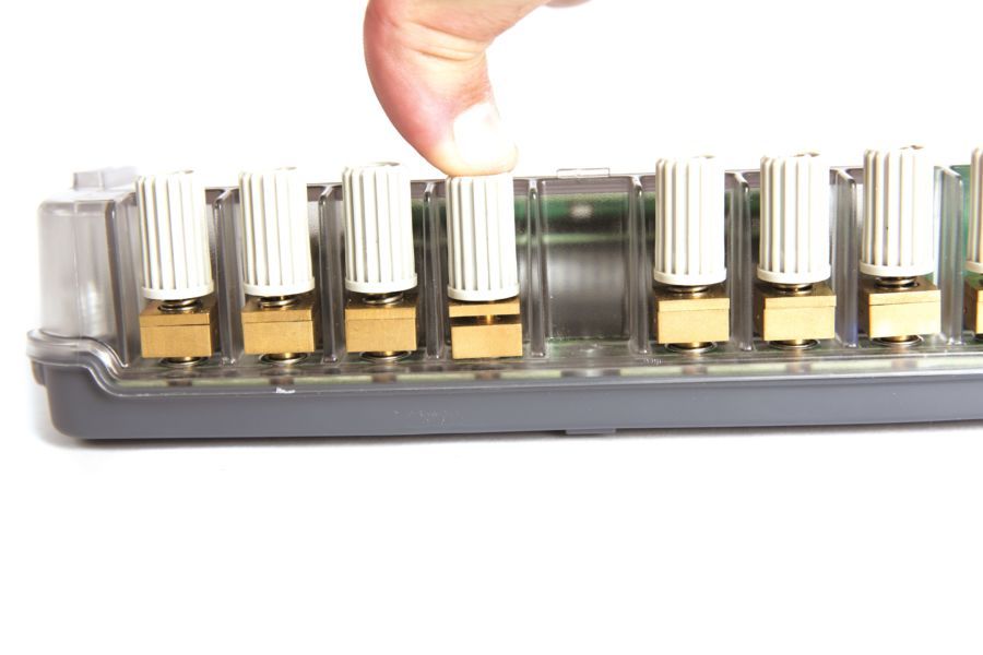
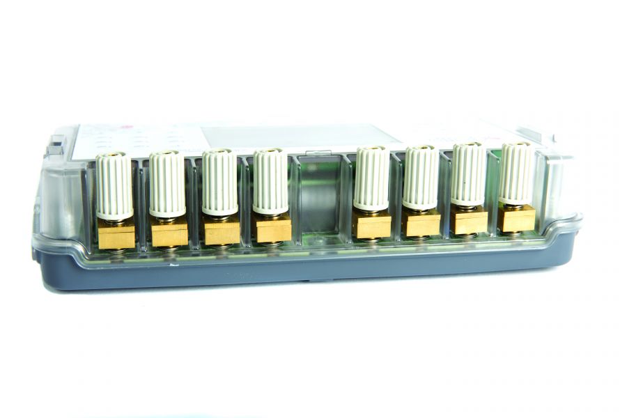
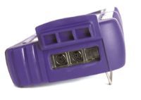
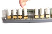
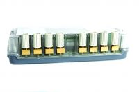
Connect your probes by simply pushing on the terminal top and insert wires of up to 3 mm or 10 AWG diameter and compensated thermocouple connectors. Wires are held tight between two brass plates ensuring thermal stability and a very good cold junction compensation for thermocouples. This system also enables 4 mm banana plugs and security connectors to be connected on the terminal top.

CALYS series, 4 models from basic use to advanced performances

Specifications CALYS 50 CALYS 75 CALYS 100 CALYS 150
Top accuracy 200 ppm 130 ppm 50 ppm
Temperature accuracy Thermocouples (14) RTDs (12) 0.013% RDG for Tc K 0.012% RDG 0.01% RDG for Tc K 0.01% RDG 0.005% RDG for Tc K 0.006% RDG
DC current + Loop supply 24 V Range Accuracy 50 mA 0.0175% RDG 100 mA 0.007% RDG
DC voltage Range Accuracy 50 V IN / 20 V OUT 0.013% RDG 50 V 0.013% RDG 50 V 0.010% RDG 50 V 0.005% RDG
Frequency Range Accuracy 20 KHz IN / 10 KHz OUT 0.005% RDG 100 KHz 0.01% RDG
Resistance Range Accuracy 4000 Ω 0.012% RDG 4000 Ω 0.010% RDG 50 KΩ 0.006% RDG
Pressure Range Accuracy   Relative pressure: 30 bar / Absolute pressure: 1,000 bar 0.05% RDG
Compliance to standards       21 CFR Part 11
      NADCAP Heat treatment AMS 2750
Additional functions Advanced data exploitation: Scaling, relative measurement, simulation of ramps and steps, synthetizer, square root, statistical functions Transmitter function
Additional functions   Switch test Calibration of transmitters
Additional functions       Comparison calibration HART: Digital calibration and data transfer Calibration of thermistors
Software   DATACAL calibration software for configuration and data management
Memory   10,000 data stored and recalled on screen as curve or list

Specifications and performances in temperature @23°C ±5°C

Uncertainty is given in % of reading (CALYS 150 display) + fixed value.

Resistive probes: Measurement and simulation

Sensor Range (Input and Output) Resolution Accuracy / 1 year (Measurement) Accuracy / 1 year (Simulation)
Pt50 (α = 3851) -220°C to +850°C 0.01°C 0.006% RDG + 0.04°C 0.006% RDG + 0.04°C
Pt100 (α = 3851) -220°C to +850°C 0.01°C 0.006% RDG + 0.03°C 0.006% RDG + 0.03°C
Pt100 (α = 3916) -200°C to +510°C 0.01°C 0.006% RDG + 0.03°C 0.006% RDG + 0.03°C
Pt100 (α = 3926) -210°C to +850°C 0.01°C 0.006% RDG + 0.03°C 0.006% RDG + 0.03°C
Pt200 (α = 3851) -220°C to +850°C 0.01°C 0.006% RDG + 0.04°C 0.006% RDG + 0.04°C
Pt500 (α = 3851) -220°C to +850°C 0.01°C 0.006% RDG + 0.03°C 0.006% RDG + 0.03°C
Pt1000 (α = 3851) -220°C to +740°C 0.01°C 0.006% RDG + 0.03°C 0.006% RDG + 0.03°C
Ni100 (α = 618) -60°C to 180°C 0.01°C 0.006% RDG + 0.05°C 0.006% RDG + 0.05°C
Ni120 (α = 672) -40°C to +205°C 0.01°C 0.006% RDG + 0.05°C 0.006% RDG + 0.05°C
Ni1000 (α = 618) -60°C to +180°C 0.01°C 0.006% RDG + 0.05°C 0.006% RDG + 0.05°C
Cu10 (α = 427) -50°C to 150°C 0.10°C 0.006% RDG + 0.18°C 0.006% RDG + 0.18°C
Cu50 (α = 428) -50°C to +200°C 0.01°C 0.006% RDG + 0.05°C 0.006% RDG + 0.05°C

Resistive probes measurements in 2, 3 or 4 wires: automatic recognition of number of connected wires, with indication on screen Accuracies are given for 4-wire mounted probes Take into account particular error of temperature sensor used and implementation conditions Admissible measuring current: 0.01 mA to 4 mA In simulation mode, specifications given for 1 mA measuring current (Pt50 / 100, Ni100 / 120, Cu10 / 50) or 0.1 mA (Pt200 / 500 / 1000, Ni1000) Temperature coefficient: < 10% of accuracy /°C

Thermocouples: Measurement and simulation

Type Input range Resolution Accuracy / 1 year (Measurement) Output range Resolution Accuracy / 1 year (Simulation)
K -250 to -200°C -200 to -120°C -120 to +1372°C 0.10°C 0.05°C 0.01°C 0.50°C 0.15°C 0.005% RDG + 0.08°C -250 to -50°C -50 to +120°C +120 to +1020°C +1020 to +1370°C 0.01°C 0.01°C 0.01°C 0.01°C 0.15% RDG 0.06°C 0.005% RDG + 0.05°C 0.007% RDG + 0.05°C
T -250 to -200°C -200 to -100°C -100 to +80°C +80 to +400°C 0.1°C 0. 01°C 0.01°C 0.01°C 0.50°C 0.05% RDG + 0.06°C 0.015% RDG + 0.07°C 0.06°C -250 to -100°C -100 to +0°C +0 to +400°C 0.01°C 0.01°C 0.01°C 0.1% RDG + 0.05°C 0.02% RDG + 0.06°C 0.055°C
J -210 to -120°C -120 to +60°C +60 to +1200°C 0.01°C 0.01°C 0.01°C 0.15°C 0.005% RDG + 0.07°C 0.0025% RDG + 0.06°C -210 to +0°C +0 to +50°C +50 to +1200°C 0.01°C 0.01°C 0.01°C 0.03% RDG + 0.08°C 0.05% RDG + 0.07°C 0.005% RDG + 0.04°C
R -50 to +150°C +150 to +550°C +550 to 1768°C 0.20°C 0.10°C 0.01°C +0.60°C +0.30°C +0.30°C -50 to +0°C +0 to +350°C +350 to +1768°C 0.01°C 0.01°C 0.01°C 0.35% RDG + 0.4°C +0.4°C +0.25°C
S -50 to +150°C +150 to +550°C +550 to +1450°C +1450 to +1768°C 0.20°C 0.10°C 0.05°C 0.05°C 0.80°C 0.30°C 0.30°C 0.35°C -50 to +0°C +0 to +350°C +350 to +1768°C 0.01°C 0.01°C 0.01°C 0.25% RDG + 0.4°C 0.30°C 0.25°C
B +400 to +900°C +900 to +1820°C 0.10°C 0.05°C 0.005% RDG + 0.4°C 0.005% RDG + 0.2°C +400 to +900°C +900 to +1820°C 0.01°C 0.01°C 0.005% RDG + 0.4°C 0.005% RDG + 0.2°C
U -200 to -100°C -100 to +660°C 0.01°C 0.01°C +0.13°C +0.09°C -200 to +400°C +400 to +600°C 0.05°C 0.05°C +0.09°C +0.11°C
N -240 to -190°C -190 to -110°C -110 to +0°C +0 to +400°C +400 to +1300°C 0.10°C 0.05°C 0.01°C 0.01°C 0.01°C 0.25% RDG 0.10% RDG 0.04% RDG + 0.06°C 0.08°C 0.005% RDG + 0.06°C -240 to -200°C -200 to +10°C +10 to +250°C +250 to +1300°C 0.01°C 0.01°C 0.01°C 0.01°C 0.15% RDG +0.10°C +0.08°C 0.008% RDG + 0.05°C

Thermocouples: PlatineL, Mo, NiMo/NiCo, G, D, L, C: For specifications, refer to the instruction manual (Available on request) Accuracy is given for reference @ 0°C. When using the internal reference junction (except couple B) add an additional uncertainty of 0.2 °C at 0 °C. It is possible (thermocouple B excepted) to choose by programming the cold junction localization: External at 0°C, internal (temperature compensation of instrument’s terminals) or manually entered. Temperature coefficient: <10% of accuracy /°C Display unit: °C and F.

Thermistors: Measurement (Channel 1)

CALYS 150_Mesure de thermistances_FR 
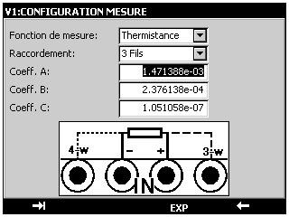
With 50 Kohms range and Steinhart – Hart equation integrated, thermistors can be entered into CALYS 150 and tested. Steinhart-hart equation is as follows:  1  = A + B (ln(R)) + C(ln(R))3 T Where: A, B and C are usually calculated according to temperature at 0°C, 25°C and 70°C

Specifications and performances in pressure @23°C ±5°C

Pressure: Measurement by external digital sensor

calys75-capteur

Range 0-1 bar 0-3 bar 0-10 bar 0-30 bar 0-100 bar 0-300 bar 0-1000 bar
Absolute X X X X X X X
Relative X X X X      

    Available in relative, absolute and differential pressure. Connector: ¼ gas Resolution: 0.02% FS Accuracy: -0.05% FS from 10 to 40°C - 0.1% FS from -10 to +10°C and from 40 to 80°C This digital pressure module ACL433 is connected to CALYS 150 through RS485 serial cable to the digital input connector. All data are digital. Measurements are compensated in temperature by a polynomial correction implemented into the firmware at factory.

Specifications and performances in process @23°C ±5°C

DC current: Measurement

With or without loop supply

Range Measurement range Res. Accuracy / 1 year Rin
0-20 mA 0 mA to 24 mA 0.1 µA 0.007% RDG + 0.8 µA < 30 Ω
4-20 mA 3 mA to 24 mA 0.1 µA 0.007% RDG + 0.8 µA < 30 Ω
100 mA 0 mA to 100 mA 0.1 µA 0.009% RDG + 2 µA < 30 Ω

Temperature coefficient: < 7 ppm/°C from 0°C to 18°C and 28°C to 50 °C Loop supply: 24 V ± 10% HART® compatibility: Input impedance Rin = 280 Ω Display with linear or quadratic scaling

DC voltage: Measurement

Range Measurement range Res. Accuracy / 1 year Rin
+100 mV -10 mV to +100 mV 1 V 0.005% RDG + 2 µV > 10 MΩ
+1 V -100mV to +1 V 10 V 0.005% RDG + 8 µV > 10 MΩ
+10 V -1 V to +10 V 100 V 0;007% RDG + 80 µV = 1 MΩ
+50 V -5 V to +50 V 1 mV 0;007% RDG + 0.5 mV = 1 MΩ

Frequency, counting: Measurement

Range Resolution Accuracy / 1 year
10 kHz < 0.01 Hz 0.01% RDG
100 kHz 0.1 Hz 0.01% RDG

Scale unit: Pulse / min and Hz Trigger level: 1 V Measurement on frequency signals or dry contacts. Counting will be performed on defined time or infinite time.

Resistance: Measurement

Range Measurement range Resolution Accuracy / 1 year
400 Ω 0 to 400 Ω 1 mΩ 0.006% RDG + 8 mΩ
3600 Ω 0 to 3600 Ω 10 mΩ 0.006% RDG + 50 mΩ
50 kΩ 0 to 50 kΩ 100 mΩ 0.008% RDG + 1 Ω

Resistance measurement in 2, 3 or 4 wires: automatic recognition of number of connected wires, with indication on screen Accuracies are given for 4-wire mounted probes

DC current: Emission

With or without loop supply

Range Resolution Accuracy / 1 year
24 mA 0.1 µA 0.007% RDG + 0.8 µA
4-20 mA 0.1 µA 0.007% RDG + 0.8 µA
0-20 mA 0.1 µA 0.007% RDG + 0.8 µA

Temperature Coefficient < 7 ppm/°C from 0°C to 18°C and 28°C to 50 °C Specifications given for CALYS 150 configurations in: - Active mode (+24V ON) 1  Meter in passive mode (+24 V OFF) - Passive mode (+24 V OFF) 1 Meter in active mode (+24 V ON) Pre-programmed steps 0%       25%      50%      75%     100% 4-20 mA linear            4          8         12         16        20 0-20 mA linear            0          5         10         15        20 4-20 mA quad             4          5          8         13        20 0-20 mA quad             0        1.25        5       11,25      20 4-20 mA valves    3.8-4—4.2               12               19, 20, 21

DC voltage: Emission

Range Emission range Res. Accuracy / 1 year Min load
+100m V -5m V to +100 mV 1 V 0.005% RDG + 2 V 1 kΩ
+1 V -5mV to +1 V 10 V 0.005% RDG + 8 V 2 kΩ
+10 V -100mV to +10 V 100 V 0.007% RDG + 80 V 4 kΩ
+50 V -100 mV to + 50 V 1 mV 0.007% RDG + 0.5 mV 4 kΩ

Frequency, pulse: Emission

Range Resolution Accuracy / 1 year
1000 Hz 0.01 Hz 0.01% RDG
100 kHz 1 Hz 0.01% RDG

Scale unit: Pulse / min and Hz Pulse emission and dry contacts simulation. Max. amplitude: 20 V (User selectable)

Resistance: Emission

Range Emission range Res. Accuracy / 1 year Nota: Iext
400 Ω 1 to 400 Ω 10 mΩ 0.006% RDG + 20 mΩ 0.1 mA / 4 mA
3600 Ω 10 to 3600 Ω 100 mΩ 0.006% RDG + 100 mΩ 0.1 mA / 4  mA
         

Emission with pulsed current available: refer to the instruction manual for specifications Temperature coefficient: < 5 ppm/°C from 0°C to 18°C and 28°C to 50 °C. Current establishing time: <1ms Compatibility with smart transmitters Iext : Current received by the calibrator

Further features

Scaling in measurement and simulation modes Scaling allows process signals to be displayed in % of FS or in all other units. This function also allows sensors to be corrected after a calibration.
Relative measurement The features allows the following :

  • Programming a reference value different from the one of the instrument (NUL function).
  • Subtracting of constant value by measuring or programming it from a measured value (TARE function).
Simulation menu Simulation value is set by entering value on keypad or by changing the specific digit with the cursor.
Square root In current measurement and simulation, this function allows taking into account a quadratic signal coming from transmitter of type ΔP.
Statistical functions Continuous display of average, minimum and maximum value of the signal under monitoring, as well as number of measurements.
Transmitters tests Transmitters can be verified using user procedures. 20 procedures can be stored as well as test results. Deviation curves are displayed. Edition of comprehensive test reports.
Switch test In temperature or pressure mode, CALYS 150 can control electronic thermostat and pressostat trigger levels.
Ramps generation Starting, ending and length time values of simple or cyclic ramps can be set to do simulation. Number of ramps can also be adjusted in case of cyclic ramps for any signals.
Steps simulation 2 modes are available:

  • Program mode: Starting value, number of steps and the length time have to be set
  • Manual mode: User has about a hundred preset values

In current simulation, user will have some additional preset values in function of range and according to 0%, 25%, 50%, 75% and 100% from selected gauge. Choice is done between gauges: 0-20 mA: linear or quadratic 4-20 mA: linear or quadratic

Synthesizer With 100 values manually set, CALYS 150 enables users to draw a generation curve.
Transmitter function CALYS 150 is able to be used as a transmitter. Measurement input is copied on the output with scaling.

General specifications

Size 210 x 110 x 50 mm
Weight 900 g
Display 240 x 320 pixel liquid crystal graphical display with backlite and contrast control Display of result as table of values or trend curve
Power supply 230 V ± 10 %, 50/60 Hz
Battery Type:lithium-ion Charging Time:  3 hours lifetime: 8hours min
Communication ports USB
Storage capacity Up to 10 full configurations (Input / output type, range…) 10,000 data into one or several measurement campaigns, i.e. more than one week work with configurations, measurements, calibration procedures and reports

Environmental specifications

Reference range 23°C ± 5°C (RH: 45 to 75 % w/o condensing)
Operating reference range -10 to 50°C (RH: 20 to 80 % w/o condensing)
Limit operating range -15°C to +55°C (RH: 10 to 80 % w/o condensing) (70% at 55°C)
Storage temperature limits -30°C to +60°C
Maximum height 0 to 2000 m
IP protection IP54 according to EN60529

Safety specifications

Protections
  • Electronic protection up to 250 V for ‘voltage’ wires
  • Fuse protection for ‘current’ wires
  • Protection against ‘current’ circuit breaking during inductive resistance measurements
Class In accordance with EN 61010-1 Category II, pollution 2
Rated voltage 60 V
Chocks and vibrations EN 61010-1
EMC conformity Immunity:

  • EN 61000-4-2
  • EN 61000-4-3
  • EN 61000-4-5
  • EN 61000-4-6
  • EN 61000-4-11

EN 61000-4-4 Conducted and radiated emissions:

  • EN 55022, class B
  • EN 61000-3-2
  • EN 61000-3-3


Instrument:

CALYS 150            On-site documenting multifunction calibrator Delivered in standard with:

  • Quick start manual
  • Battery charger
  • Set of 6 testing leads
  • Carrying strap
  • Factory test report

Accessories:

ACL433                 External digital pressure sensor for CALYS 75 / 100 / 150 (Absolute or relative pressure) Different ranges available from 0 to 1,000 bar Range from -1 -> 1; 3; 10; 30 (absolute or relative pressure) Range from -1 -> 100; 300; 1,000 (absolute pressure only) Standard accuracy: 0.05% FS AN6050                 Transport case for CALYS series ACL9311                Set of 6 measuring cables with removable crocodile clips ACL500                 Hart modem for CALYS 150 ACL600                 Cable to drive temperature dry blocks and baths for CALYS 150 Please ask before for compliance with your bath / dry-block.

Software:

DATACAL              Calibration software for CALYS 75 / 100 / 150 Supplied with USB cable

Certification:

QMA11EN              COFRAC certificate of calibration With all relevant data points where the device has been tested AMS 2750              Compliance certificate to NADCAP AMS 2750 standard

Packing information:

Size                       210 mm x 110 mm x 50 mm Weight without packing   900 g

Product Description Release Type
CALYS 150 firmware

Firmware

B.13 exe
CALYS 150 INST MANUAL

Instruction manual

NTA47224-300A11 NTA47224-300A11 - Mode d
CALYS 150 manual es/de/it

Instruction manual in German, Spanish, Italian

NTA47224-600A11 NTA47224-600A11 - Mode d
CALYS 150 scpi

SCPI commands

V1.3 pdf
DATACAL

Data management software

2.10 exe
DATACAL

Instruction manual in English

2.7 pdf
DATACAL

Manuale d’istruzione

2.7 pdf