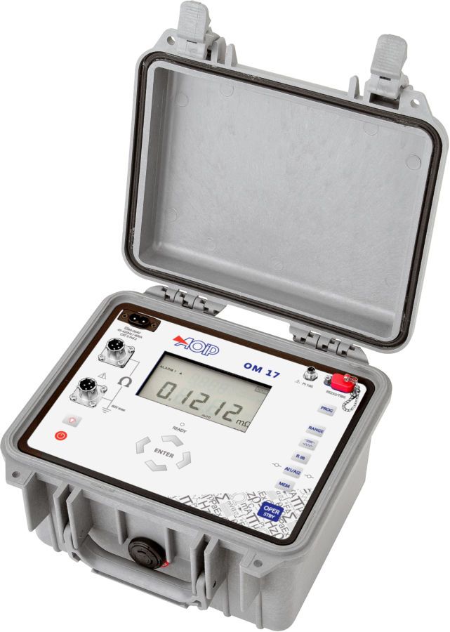
OM 17 (1) - AOIP, Instrumentation de test et mesure, contrôle moteur

OM 17

picto fleche Field 10 A micro-ohmmeter for inductive and non-inductive resistance

Succeeding OM 16, OM 17 offers upgraded performances, in particular for inductive resistance measurements: Granted with a greater autonomy, OM 17 allows longer test campaigns to be performed at 10 A with continuous current (up to 60 min) and offers faster current loading of coil resistances (stabilization time < 2 s).

Easy to use, it carries out 4-wire measurements of inductive and non-inductive resistance with a continuous or pulse current up to 10 A. Offering a high precision of 0.05% and a 0.1 µΩ resolution, it has a different ranges selectable from 5 mΩ to 2.5 kΩ.

Ask a question
Get a call

Designed for field use -in workshops or outdoors-, OM 17 micro-ohmmeter is a field instrument, whose performances are as high as a laboratory instruments’. Succeeding OM 16, OM 17 offers upgraded performances, in particular for inductive resistance measurements: Granted with a greater autonomy, OM 17 allows longer test campaigns to be performed at 10 A with continuous current (up to 60 min) and offers faster current loading of coil resistances (stabilization time < 2 s). Easy to use, it carries out 4-wire measurements of inductive and non-inductive resistance with a continuous or pulse DC current up to 10 A. Offering a high precision of 0.05% and a 0.1 µΩ resolution, it has a different ranges selectable from 5 mΩ to 2.5 kΩ.

Key features:

  • 4-wire measurement of inductive and non-inductive resistance
  • Continuous or pulse DC current, from 1 mA to 10 A
  • Precision: 0.05% Reading
  • Automatic EMF compensation
  • Ambient temperature compensation (measured or programmed)
  • Compensation of metal temperature coefficient
  • Choice of reference temperature
  • 2 programmable thresholds with visual and sound alarm
  • Memory: 1,000 measurements identified
  • Ideal for long tests at 10 A continuous over transformers

Easy to use, rugged and protected against rough environment (IP 53 when opened / IP 64 when closed, lockable measurement plugs), OM 17 is widely recommended for indoor and outdoor use in many industries:

  • Aerospace
  • Energy field
  • Domestic electrical appliances
  • Cable manufacturing
  • Telecommunication
  • Electronics
  • Automotive industry
  • Railway

Various fields of applications

  • Metallization and earth bonding control
  • Welding quality control
  • Contact resistance measurement (low voltage connectors, relays…)
  • Test of electronic components
  • Coil, transformer and motor resistance measurement, loss and heat rise calculation
  • Non-twisted and twisted cable resistivity measurement and length calculation
  • Railway and electric network maintenance

Two current waveforms

Continuous DC current

  • Inductive resistance and coils
  • Automatic trigger of measurements when using a trigger test probe
  • EMF compensation before measurements

Courant pulsé

  • Non-inductive resistance
  • Automatic trigger of measurements as continuity is established – 1 operator needed
  • Automatic current shutdown at the end of a measurement
  • EMF compensation before every measurement

Configuration and display

OM 17_Ecran_2All parameters are user-programmable, either directly through the instrument interface or via software (LOG OM, available in option) : Measuring current, range, resistance type, unit, reference temperature, alarm threshold value & status and calculation... OM 17 large display informs the operator in real time about the measurement itself and the measuring conditions. Any detection of range overshoot, open circuit or low battery is indicated by LEDs and message displayed on the screen. Before every measurement, EMFs are measured and automatically removed for a greater accuracy of measurements. For non-inductive resistances, a single operator is enough to perform the measurement since it will be automatically triggered once continuity is established between the two points. The user can also set the metal nature or its temperature coefficient, the reference temperature and the ambient temperature. The ambient temperature might be also measured by an external temperature probe. Battery-powered, OM 17 has a high storage capacity of 1,000 measurements to be read directly on the display or via Log OM software. Protection up to 250 V is ensured at every measurement terminal, while any overrange, open circuit or empty battery signal detected is notified by LEDs and messages displayed.

Performances and technical specifications @23°C ±5°C

Uncertainty is given in % of reading + fixed value.

Resistance measurement

Measurement range Resolution Accuracy / 1 year (23°C ±5°C) Measuring current Voltage drop
5 mΩ 0.1 μΩ 0.05 % + 1 μΩ 10 A 50 mV
25 mΩ 1 μΩ 0.05 % + 3 μΩ 10 A 250 mV
250 mΩ 10 μΩ 0.05 % + 30 μΩ 10 A 2.5 V
2500 mΩ 0.1 mΩ 0.05 % + 0.3 mΩ 1 A 2.5 V
25 Ω 1 mΩ 0.05 % + 3 mΩ 100 mA 2.5 V
250 Ω 10 mΩ 0.05 % + 30 mΩ 10 mA 2.5 V
2500 Ω 100 mΩ 0.05 % + 300 mΩ 1 mA 2.5 V

Automatic or manual selection of measurement range Possible excess over the nominal range:

  • 5 mΩ range: + 20 %
  • 25 mΩ range: + 20 %

Maximum voltage between the terminals in an open circuit: 7 V Current waveform: Continuous or pulse DC current

Ambient temperature measurement for Tref compensation

Type Resolution Precision / 1 year (23°C ±5°C) Comment
Pt100 0.1°C 0.5°C Measured with external Pt100 or value entered by keyboard

Typical measurement campaigns of inductive resistances (on rotors / stators 1-3 m3)

Tested coil Typical measured value (mΩ) 1st measure delay (s) Total campaign duration (minutes) Nb measures executed Configuration
Type        Résistance OM 17 OM 16 OM 17 OM 16 OM 17 OM 16 OM 17 OM 16 Range Current
1 rotor phase (~ 0,5 H) 1 mΩ 1.2371 1.2371(1) 1.2382(2) < 1 ~ 2 > 20 ~ 40 s(1) ~ 20 s(2) >10,000 ~ 320(1) ~ 150(2) 5 mΩ 10 A
1 stator phase (~ 0,5 H) 3 mΩ 3.0008 3.0008 < 1 ~ 2 > 30 < 1 > 15,000 < 500 5 mΩ 10 A
Transfo (~ 1 H) 150 mΩ 150.13 150.13 < 2 ~ 3 > 45 < 2 > 22,500 < 1,000 250 mΩ 10 A
3 motor phases 980 mΩ 980.3 980.3 < 1 ~ 2 > 10 > 10 > 5,000 > 5,000 2,500 mΩ 1 A

(1) Measurement at cold condition, at instrument start      (2) Measurement at hot condition, after a 1st test campaign

Further features

Resistance types
  • Inductive resistances: Coils, transformers, motor windings, twisted cables...
  • Non-inductive resistances: Earth bonding, coating, contact résistances, non-twisted cables...
Measurement trigger conditions Manual or automatic trigger allowing a single operator to be able to perform measurements
EMFs Automatic compensation of EMF parasites before each measurement for a greater accuracy
Temperature compensation - Ambient temperature Tamb, measured with external Pt100 (or entered by the user - Programmed reference temperature Tref, to which the measured value is converted: R(Tref) = [R(Tamb) * (1 + α * Tref)] / [1 + α * Tamb] - Metal material, whose temperature coefficient can be entered by the user (α)
Temperature coefficient beyond operating range <10% accuracy/°C (from 0 to18°C and from 28 to 50°C)
Alarms 2 programmable thresholds with visuel and sound signal

General specifications

Size L x W x H 270 x 250 x 180 mm
Weight 4 kg
Power supply 100 to 240 V (50 / 60 Hz)
Battery Type: Ni/Mh 8.5 Ah (Taille D) Charging time: 5 h Battery life: > 5000 values (pulse current), > 60 min (10 A continuous current, 250 mΩ range)
Communication ports RS 232
Storage capacity 1,000 measurements identified by numbers Memory reading directly on the display, via software or printer

Environmental specifications

Reference range 23°C ± 5°C (RH: 45 to 75 % w/o condensing)
Operating reference range 0 to 50°C (RH: 20 to 75 % w/o condensing)
Limit operating range -10°C to +55°C (RH: 10 to 80 % w/o condensing)
Storage temperature limits -40°C to +60°C (-15°C to +50°C with battery charged)
IP protection IP53 opened /  IP64 closed, according to EN 60529

Safety specifications

Protections
  • Electronic protection up to 250 V for ‘voltage’ wires
  • Fuse protection for ‘current’ wires
  • Protection against ‘current’ circuit breaking during inductive resistance measurements
Rated voltage 60 V
Electric safety EN 61010-1
EMC conformity EN 61326 Immunity:

  • Electrostatic discharge: EN 61000-4-2
  • Radiated fields: EN 61000-4-3
  • Surge: EN 61000-4-5
  • Conducted disturbances: EN 61000-4-6
  • Voltage dips: EN 61000-4-11
  • Bursts: EN 61000-4-4

Conducted and radiated emissions:

  • EN 55022, class B
  • EN 61000-3-2
  • EN 61000-3-3

Instrument:

OM17                  On-site micro-ohmmeter                            

Supplied in standard with:                          
- Standard mains supply cable to recharge the battery                            
- Quick start manual

Clips and probes:

Please note that 2 clips are needed per instrument.
AMT005              Long handspike, per unit                             Needle diameter: 3 mm, length without handle: 83 mm, total length: 215 mm, cable length: 5 m
AMT006              Large kelvin clip, per unit                             Opening diameter: 25 mm, cable length: 5 m
AMT011              Small handspike, per unit                             Needle diameter: 3 mm, total length: 125 mm, cable length: 5 m
AMT012              Small kelvin clip, per unit                             Opening diameter: 12 mm, cable length: 5 m
AMT013              Triggered handspike, per unit Needle diameter: 3 mm, length without handle 83 mm, total length: 215 mm, cable length: 5 m Triggering cable to be connected by RS 232 AMT008              Extension lead, length: 20 m
AMT014              External Pt100 temperature sensor
AMT015              Extension cable for AMT014, length: 2 m

Other accessories:

LOG OM             Configuration & exploitation software for OM 17 - Includes a F / F RS 232 cable
AN5909              RS232 F / F cable (PC connection) AN5875              RS232 F / M cable (Printer connection)

Certification:

QMA11EN          COFRAC certificate of calibration

Packing information:

Size                    270 x 250 x 180 mm Weight                4 kg

Product Description Release Type
instruction manual OM 17

instruction manual for OM17 microhmmeter

V06 pdf