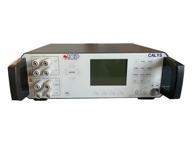
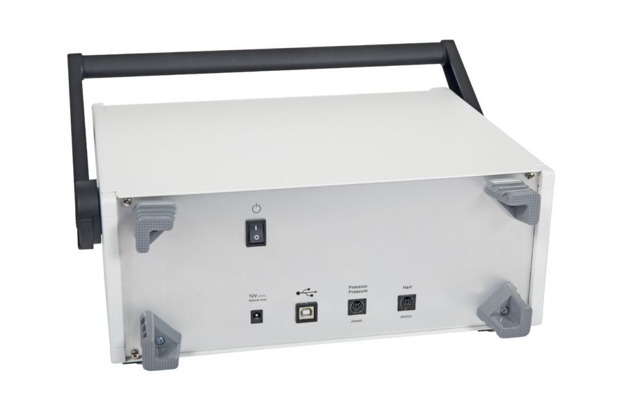
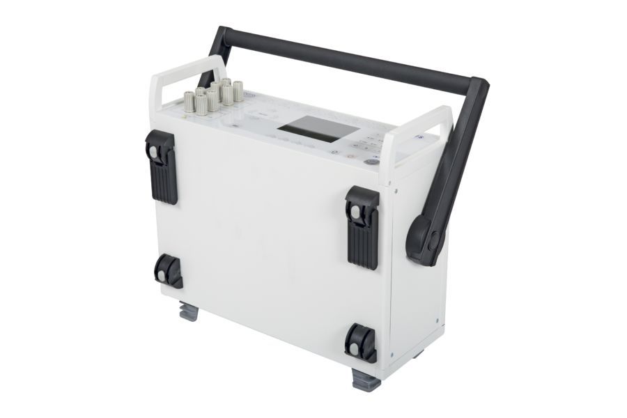
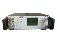
CALYS 1500 (1) - AOIP, Instrumentation de test et mesure, contrôle moteur
CALYS 1500 advanced laboratory electrical calibrator

CALYS 1500

picto fleche Advanced laboratory electrical calibrator / Dual input thermometer

CALYS 1500, most advanced and accurate laboratory electrical calibrator of the range, does not only work as a simulator (IN / OUT) but also as a dual channel thermometer (IN / IN) to perform comparison calibration. It calibrates HART transmitters (HART communicator) and thermistors.

Ask a question
Get a call

CALYS 1500, most advanced and accurate laboratory electrical calibrator of the range, does not only work as a simulator (IN / OUT) but also as a dual channel thermometer (IN / IN) to perform comparison calibration. It calibrates HART transmitters (HART communicator) and thermistors. It is the perfect tool for advanced process maintenance and use on test bench in all industries. Suitable for all field and lab measurements, it can simultaneously measure and generate over two isolated channels various signals of temperature, resistance, process, pressure and frequency in one single instrument. Providing extended functionalities (temperature simulation, scaling, steps, synthesizer, statistical functions…) and audit trails, CALYS 150 complies with both 21 CFR Part 11 and NADCAP Heat Treatment standards and makes advanced data exploitation and full data traceability easier. 10 full configurations can be saved and recalled by the user or the user group, making CALYS 1500 the ideal tool for regular and repeated tasks. High performances in measurement and simulation for CALYS 1500:

  • Temperature Up to 0.005 % RDG
  • Resistance Up to 0.006 % RDG and 50 KΩ range
  • Current: Up to 0.007 % RDG and 100 mA range + Loop Supply 24 V
  • Voltage: Up to 0.005 % RDG and 50 V range
  • Frequency: Up to 0.01 % RDG and 100 KHz range
  • Pressure: With an external pressure module (comparison calibration with a pressure pump)

Calibration procedures and DATACAL software

Using this user-friendly instrument, calibration tasks can be quickly carried out over the whole process chain. Take the documenting process calibrator to the field with you during the whole week with 10 calibration procedures stored in the device. Run the procedure after connecting the probes to the instrument and save the results for onsite easy and quick calibration. Back to the office, you can then upload the data on a computer in order to issue customized calibration certificates with dedicated calibration software DATACAL.  

Innovative and ergonomic design

  • Metal housing for enhanced robustness
  • Capacitive touch panel
  • USB communication
  • Carrying handle
  • Battery and main powered

CALYS 1500, calibrateur électrique de laboratoire

Graphic screen and display resolution

CALYS 1500 allows the digit number after the dot to be selected: This function is justified by the needs of users who want or not to display the best resolution for calibration or on the contrary limit it for simple verifications. CALYS 1500 dual display indicates permanently the measurement value, and also the emitted value, the gauge and the used functions. On the top date, time and also external temperature are also indicated. During measuring average, maximum, minimum and the number of measurements are displayed on the left. While for emission this part of screen displays all details of ramps, steps and constant value emission functions. Drop-down menus are used with the navigator, and an on-line help is available to make easier connections of probes and wires.

Specifications and performances in temperature @23°C ±5°C

Uncertainty is given in % of reading (CALYS 1500 display) + fixed value.

Resistive probes: Measurement and simulation

SensorRange (Input and Output)ResolutionAccuracy / 1 year (Measurement)Accuracy / 1 year (Simulation)
Pt50 (α = 3851)-220°C to +850°C0.01°C0.006% RDG + 0.04°C0.006% RDG + 0.04°C
Pt100 (α = 3851)-220°C to +850°C0.01°C0.006% RDG + 0.03°C0.006% RDG + 0.035°C
Pt100 (α = 3916)-200°C to +510°C0.01°C0.006% RDG + 0.03°C0.006% RDG + 0.035°C
Pt100 (α = 3926)-210°C to +850°C0.01°C0.006% RDG + 0.03°C0.006% RDG + 0.035°C
Pt200 (α = 3851)-220°C to +850°C0.01°C0.006% RDG + 0.04°C0.006% RDG + 0.04°C
Pt500 (α = 3851)-220°C to +850°C0.01°C0.006% RDG + 0.03°C0.006% RDG + 0.04°C
Pt1000 (α = 3851)-220°C to +740°C0.01°C0.006% RDG + 0.03°C0.006% RDG + 0.035°C
Ni100 (α = 618)-60°C to +180°C0.01°C0.006% RDG + 0.05°C0.006% RDG + 0.04°C
Ni120 (α = 672)-40°C to +205°C0.01°C0.006% RDG + 0.05°C0.006% RDG + 0.04°C
Ni1000 (α = 618)-60°C to +180°C0.01°C0.006% RDG + 0.05°C0.006% RDG + 0.04°C
Cu10 (α = 427)-50°C to +150°C (Mes) -70°C to +150°C (Sim)0,10°C (Mes)  0.01°C (Sim)0.006% RDG + 0.18°C0.006% RDG + 0.1°C
Cu50 (α = 428)-50°C to +200°C0.01°C0.006% RDG + 0.05°C0.006% RDG + 0.05°C

Temperature coefficient: < 10% of accuracy /°C beyond reference domain Resistive probes measurements in 2, 3 or 4 wires: automatic recognition of number of connected wires, with indication on screen Accuracies are given for 4-wire mounted probes Take into account particular error of temperature sensor used and implementation conditions Admissible measuring current: 0.25 mA (Measurement) or 0.1 mA to 1 mA (Emission)

Thermocouples: Measurement and simulation

TypeInput range ResolutionAccuracy / 1 year (Measurement)Output rangeResolutionAccuracy / 1 year (Simulation)
K-250 to -200°C -200 to -120°C -120 to +1372°C0.10°C 0.05°C 0.01°C0.50°C 0.15°C 0.005% RDG + 0.08°C-250 to -50°C -50 to +120°C +120 to +1020°C +1020 to +1370°C0.01°C 0.01°C 0.01°C 0.01°C0.15% RDG 0.06°C 0.005% RDG + 0.05°C 0.007% RDG + 0.05°C
T-250 to -200°C -200 to -100°C -100 to +80°C +80 to +400°C0,1°C 0,01°C 0,01°C 0.01°C0.50°C 0.05% RDG + 0.06°C 0.015% RDG + 0.07°C 0.06°C-250 to -100°C -100 to +0°C +0 to +400°C0.01°C 0.01°C 0.01°C0.1% RDG + 0.05°C 0.02% RDG + 0.06°C 0.055°C
J-210 to -120°C -120 to +60°C +60 to +1200°C0.01°C 0.01°C 0.01°C0.15°C 0.005% RDG + 0.07°C 0.0025% RDG + 0.06°C-210 to -0°C +0 to +50°C +50 to +1200°C0.01°C 0.01°C 0.01°C0.03% RDG + 0.08°C 0.05% RDG + 0.07°C 0.005% RDG + 0.04°C
E-250 to -200°C -200 to +100°C +100 to 1000°C0,05°C 0,01°C 0.01°C0.30°C 0.06°C 0.005% RDG + 0.05°C-250 to +40°C +40 to +550°C +550 to +1000°C0.01°C 0.01°C 0.01°C0.15°C 0.005% RDG + 0.12°C 0.005% RDG + 0.13°C
R-50 to +150°C +150 to +550°C +550 to 1768°C0,2°C 0,1°C 0.01°C0.60°C 0.30°C 0.30°C-50 to +0°C +0 to +350°C +350 to 1768°C0.01°C 0.01°C 0.01°C0.35% RDG + 0.4°C 0.04°C 0.25°C
S-50 to +150°C +150 to +550°C +550 to +1450°C +1450 to +1768°C0.20°C 0.10°C 0.05°C 0.05°C0.80°C 0.30°C 0.30°C 0.35°C-50 to +0°C +0 to +350°C +350 to +1768°C0.01°C 0.01°C 0.01°C0.25% RDG + 0.4°C 0.30°C 0.25°C
B+400 to +900°C +900 to +1820°C0.1°C 0.05°C0.005% RDG + 0.4°C 0.005% RDG + 0.2°C+400 to +900°C +900 to +1820°C0.01°C 0.01°C0.005% RDG + 0.4°C 0.005% RDG + 0.2°C
U-200 to -100°C -100 to +660°C0,01°C 0.01°C0.13°C 0.09°C-200 to +400°C +400 to +660°C0.05°C 0.05°C0.09°C 0.11°C
L-200 to +900°C0.01°C0.10°C-200 to +900°C0.05°C0.15°C
C-20 to +900°C +900 to +1730°C +1730 to °C0.05°C 0,05°C 0,05°C0.15°C 0.008% RDG + 0.12°C 0.015% RDG + 0.12°C-20 to +1540°C +1540 to +2310°C0.10°C 0.10°C0.25°C 0.012% RDG + 0.1°C
N-240 to -190°C -190 to -110°C -110 to +0°C +0 to 400°C +400°C to +1300°C0,10°C 0.05°C 0.01°C 0.01°C 0.01°C0.25% RDG 0.10% RDG 0.04% RDG + 0.06°C 0.08°C 0.005% RDG + 0.06°C-240 to -200°C -200 to +100°C +10 to +250°C +250 to +1300°C0.01°C 0.01°C 0.01°C 0.01°C0.15% RDG 0.10°C 0.08°C 0.008% RDG + 0.05°C
Platine-100 to +100°C +100 to +1400°C0.01°C 0.01°C0.15°C 0.005% RDG + 0.06°C-100 to +1400°C0.05°C0.10°C
Mo+0 to +1375°C0.01°C0.005% RDG + 0.06°C+0 to +1375°C0.05°C0.005% RDG + 0.06°C
NiMo/NiCo-50 to +1410°C0.01°C0.005% RDG + 0.30°C-50 to +1410°C0.05°C0.005% RDG + 0.3°C

Temperature coefficient: < 5% of accuracy /°C beyond reference domain Accuracy is given for reference @ 0°C. When using the internal reference junction (except couple B) add an additional uncertainty of 0.2 °C at 0 °C. It is possible (thermocouple B excepted) to choose by programming the cold junction localization: External at 0°C, internal (temperature compensation of instrument’s terminals) or manually entered. Display unit: °C? F and K. Thermocouples: G, D: For specifications, refer to the instruction manual (Available on request)

Specifications and performances in pressure @23°C ±5°C

calys75-capteurPressure: Measurement by external digital sensor

Range0-1 bar0-3 bar0-10 bar0-30 bar0-100 bar0-300 bar0-1000 bar
AbsoluteXXXXXXX
RelativeXXXX   

Available in relative, absolute and differential pressure. Connector: ¼ gas Resolution: 0.02% FS Accuracy: -0.05% FS from 10 to 40°C - 0.1% FS from -10 to +10°C and from 40 to 80°C This digital pressure module ACL433 is connected to CALYS 1500 through RS485 serial cable to the digital input connector. All data are digital. Measurements are compensated in temperature by a polynomial correction implemented into the firmware at factory.

Specifications and performances in process @23°C ±5°C

DC current: Measurement

With or without loop supply

RangeResolutionAccuracy / 1 year Nota: Rin
0-20 mA0.1 µA0.007% RDG + 0.8 µA< 30 Ω
4-20 mA0.1 µA0.007% RDG + 0.8 µA< 30 Ω
±100 mA0.1 µA0.007% RDG + 2 µA< 30 Ω

Temperature coefficient: < 7% of accuracy /°C beyond reference domain Loop supply: 24 V ±10% HART® compatibility: Input impedance Rin = 280 Ω CALYS 1500 also allows linear or quadratic signals to be linearized. Specifications given for CALYS configurations in: - Active mode (+24V ON) 1 Meter in passive mode (+24 V OFF) - Passive mode (+24 V OFF) 1 Meter in active mode (+24 V ON)

Direct voltage: Measurement

RangeFull rangeResolutionAccuracy / 1 year Nota: Rin
100 mV-10 mV to 100 mV1 µV0.005% RDG + 2 µV> 10 MΩ
1 V (1)-100 mV to 1 V10 µV0.005% RDG + 8 µV> 10 MΩ
10 V-1 V to 10 V100 µV0.007% RDG + 80 µV= 1 MΩ
50 V-5 V to 50 V1 mV0.007% RDG + 0.5 mV= 1 MΩ

Temperature coefficient: < 5% of accuracy /°C beyond reference domain

Frequency and counting: Measurement

RangeFull rangeResolutionAccuracy / 1 year
10 KHz1 Hz to 10 KHz0.1 Hz0.005% RDG + 5 mHz
100 KHz10 Hz to 100 KHz0.1 Hz0.005% RDG + 5 mHz

Temperature coefficient: < 5 ppm/°C beyond reference domain Scale unit: Pulse / min and Hz Trigger level: 1 V Measurement on frequency signals or dry contacts Counting will be performed on defined time or infinite time

Resistance: Measurement

RangeResolutionAccuracy / 1 year
400 Ω1 mΩ0.006% RDG + 8 mΩ
3600 Ω10 mΩ0.006% RDG + 50 mΩ
50 KΩ (1)100 mΩ0.008% RDG + 1 Ω

(1) Range on channel 1 only. Temperature coefficient: < 7 ppm/°C beyond reference domain 2, 3 or 4 wires resistance measurement: automatic recognition of number of connected wires, with indication on screen Accuracies are given for 4-wire mounted probes Open circuit terminal voltage: < 10 V Continuity test: Open circuit for R > 1000 Ω and closed circuit for R < 1000 Ω

DC current: Emission

CalibreRésolutionPrécision / 1 anNote
24 mA1 µA0,007% L + 0,8 µAWith or without loop supply (24 V)
4-20 mA1 µA0,007% L + 0,8 µA
0-20 mA1 µA0,007% L + 0,8 µA

Temperature coefficient: < 7 ppm/°C beyond reference domain Settling time: < 5 ms Specifications given for CALYS configurations in: - Active mode (+24V ON) 1 Meter in passive mode (+24 V OFF) - Passive mode (+24 V OFF) 1 Meter in active mode (+24 V ON) Pre-programmed steps

 0%25%50%75%100%
4-20 mA linear48121620
0-20 mA linear05101520
4-20 mA quad4581320
0-20 mA quad01.25511.2520
4-20 mA valves3.8-4-4.2 12 19, 20, 21

Direct voltage: Emission

RangeFull rangeResolutionAccuracy / 1 year Minimum output load
100 mV-5 mV to 100 mV1 µV0.005% RDG + 2 µV1 KΩ
1 V-5 mV to 1 V10 µV0.005% RDG + 8 µV2 KΩ
10 V-100 mV to 10 V100 µV0.007% RDG + 80 µV4 KΩ
50 V-100 mV to 50 V1 mV0.007% RDG + 0.5 mV4 KΩ

Temperature coefficient: < 5 ppm/°C beyond reference domain

Frequency and pulses: Emission

RangeResolutionAccuracy / 1 year
1000 Hz0.01 Hz0.005% RDG + 5 mHz
100 KHz1 Hz0.005% RDG + 5 mHz

Temperature coefficient: < 5 ppm/°C beyond reference domain Scale unit: Pulse / min and Hz Pulse emission and dry contact simulation Max amplitude: 20 V selectable by user

Resistance: Emission

RangeFull range ResolutionAccuracy / 1 year Notes
400 Ω - 1 mA (Direct current)1 Ω to 400 Ω10 mΩ0.006% RDG + 20 mΩIext : 0.1 mA - 1 mA
400 Ω - 1 mA (Pulsed current)1 Ω to 400 Ω10 mΩ0.006% RDG + 30 mΩIext : 0.1 mA - 1 mA
400 Ω - 4 mA (Direct current)1 Ω to 400 Ω10 mΩ0.006% RDG + 20 mΩIext : 1 mA - 4 mA
400 Ω - 4 mA (Pulsed current)1 Ω to 400 Ω10 mΩ0.006% RDG + 30 mΩIext : 1 mA - 4 mA
3600 Ω (Direct current)10 Ω to 3600 Ω100 mΩ0.006% RDG + 100 mΩIext : 0.1 / 1 mA
3600 Ω (Pulsed current)10 Ω to 3600 Ω100 mΩ0.006% RDG + 200 mΩIext : 0.1 / 1 mA

Temperature coefficient: < 5 ppm/°C beyond reference domain Iext : Current received by the calibrator

Further functionalities

File MenuUsers can save up to 10 full configurations of the instruments and recall them. Configurations include all programming done on instrument.
Scaling in measurement and simulation modesScaling allows process signals to be displayed in % of FS or in all other units. This function also allows sensors to be corrected after a calibration.
Relative measurementThe features allows the following :

  • Programming a reference value different from the one of the instrument (NUL function).
  • Subtracting of constant value by measuring or programming it from a measured value (TARE function).
Simulation menuSimulation value is set by entering value on keypad or by changing the specific digit with the cursor.
Square rootIn current measurement and simulation, this function allows taking into account a quadratic signal coming from transmitter of type ΔP.
Statistical functionsContinuous display of average, minimum and maximum value of the signal under monitoring, as well as number of measurements.
Transmitter testTransmitters can be verified using user procedures. 20 procedures can be stored as well as test results. Deviation curves are displayed. Edition of comprehensive test reports.
Switch testIn temperature or pressure mode, CALYS 1500 can control electronic thermostat and pressostat trigger levels.
Ramps generationStarting, ending and length time values of simple or cyclic ramps can be set to do simulation. Number of ramps can also be adjusted in case of cyclic ramps for any signals.
Steps simulation2 modes are available:

  • Program mode: Starting value, number of steps and the length time have to be set
  • Manual mode: User has about a hundred preset values

In current simulation, user will have some additional preset values in function of range and according to 0%, 25%, 50%, 75% and 100% from selected gauge. Choice is done between gauges:

  • 0-20 mA: linear or quadratic
  • 4-20 mA: linear or quadratic
SynthesizerWith 100 values manually set, CALYS 1500 enables users to draw a generation curve.
Transmitter functionCALYS 1500 is able to be used as a transmitter. Measurement input is copied on the output with scaling.
Memory capacityUp to 10 full configurations (Input / output type, range…) 10,000 data into one or several measurement campaigns, i.e. more than one week work with configurations, measurements, calibration procedures and reports.

General specifications

Size (L x W x h)340 x 320 x 160 mm
Weight4.6 Kg
Display240 x 320 pixel liquid crystal graphical display with backlite & contrast control Display of result as table of values or trend curve
Power supply230 V ±10 %, 50/60 Hz
BatteryType: Lithium-Ion Charging time: 3 hours Lifetime: 8 hours
Communication portsUSB

Environmental specifications

Reference range23°C ±5°C (HR : 45 to 75 % w/o condensing)
Operating reference range-10 to 50°C (HR : 20 to 80 % w/o condensing)
Limit operating range-15 to 55°C (HR : 10 to 80 % w/o condensing) (70% at 55°C)
Storage temperature limits-30°C to +60°C
Maximum height0 to 2000 m
IP protectionIP54 according to EN 60529

Safety specifications

Protections
  • Electronic protection up to 250 V for ‘voltage’ wires
  • Fuse protection for ‘current’ wires
  • Protection against ‘current’ circuit breaking during inductive resistance measurements
ClassIn accordance with EN 61010-1
Rated voltage60 V
Chocks and vibrationsEN 61010-1
EMC conformityEN 61326-1, CEM 2004/108/CE

Instrument:

CALYS 1500            Benchtop precision documenting multifunction calibrator Delivered in standard with:

  • Quick start manual
  • Battery charger
  • Set of 6 testing leads
  • Factory test report

Accessories:

ACL433                External digital pressure sensor, range to be specified at the order: Absolute or relative pressure: Range from -1 -> 1; 3; 10; 30 bar Absolute pressure: Range from -1 -> 100; 300; 1000 bar ACL9311               Set of 6 measuring cables with removable crocodile clips ER 49504-000        USB cable ACL500                 Hart modem for CALYS 150 ACL600                 Cable to drive temperature dry blocks and baths for CALYS 150 Please ask before for compliance with your bath / dry-block

Logiciel :

Software:

DATACAL              Calibration software for CALYS 1000 / 1200 / 1500 Supplied with USB cable

Certification:

QMA11EN             COFRAC certificate of calibration With all relevant data points where the device has been tested AMS 2750             Compliance certificate to NADCAP AMS 2750 standard

Packing information:

Size                      340 x 320 x 160 mm Weight without packing  4,6 Kg

ProductDescriptionReleaseType
Calys 1500 firmware

Firmware

A.011exe
CALYS 1500 instr manual

Instruction manual

NTA47271-300A6pdf
CALYS 1500 scpi

SCPI commands

1.3pdf
DATACAL

Instruction manual in English

2.7pdf
DATACAL

Manuale d’istruzione

2.7pdf