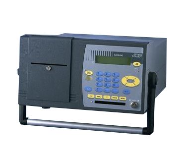
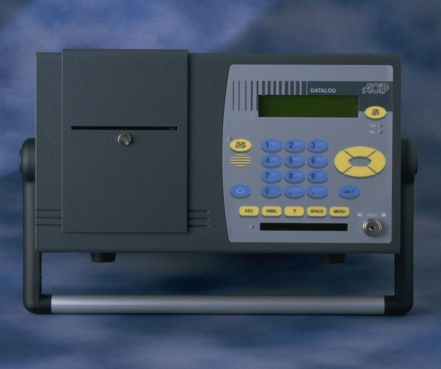
DATALOG 20 / 90 / 140
 Modular data acquisition system with 2, 9 or 14 input / output boards
DATALOG series of data acquisition systems (2, 9 or 14 input / output boards) are aiming to measure, condition, process, monitor and record analogue and digital signals from all common types of physical sensors.
- DC and AC voltage, current, resistance, strain gauges
- Temperature: Thermocouples, resistive probes
- Dry contacts
- Communication: Modbus RS485, RS 233
Ask a question
Get a call
